Modeling and Subdivision in Cheetah3D - A Screwdriver

Cheetah3D (C3D) is a well-appointed 3D modeling and rendering software package for Mac. If you don't have Mac or C3D, you may still refer to the general "box" modeling approach shown below, but the features available in your software may not translate precisely. Out of the various approaches to 3D modeling (Spline, Box, or Polygon), C3D's primary strength for me personally is box modeling. Splines and polygon modeling are supported. However, box modeling in C3D just feels good. Also, it is a lot of fun!
What I discuss in this post is one possible solution for how to get started making an image like the one shown below by modeling the handle of the screwdriver. This entire model, the textures, lighting, and final render were created with C3D. The irony in my life is that I almost always find a Flathead screwdriver when I really need a Phillips head, so I decided to keep this trend here.

C3D does lack some features that I find desirable. As of version 6, volumetric lighting, sub-surface scattering, and fur modeling are not yet supported. Even without these features, C3D is excellent at most tasks in 3D modeling and has a very approachable user interface. So let's get started on that handle.
Step 1:
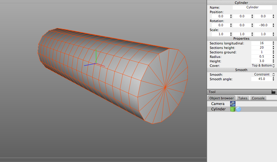
Create a default parametric Cylinder. Once the object is in your 3D view, change the values of the following parameters or customize as you see fit. (Sections = 16x20, Height = 3). The default orientation of the cylinder will also be vertical along the Y axis. You may wish to rotate the cylinder along the X or Z axis to align it horizontally. In this example, I rotated the cylinder by 90 degrees.
Step 2:
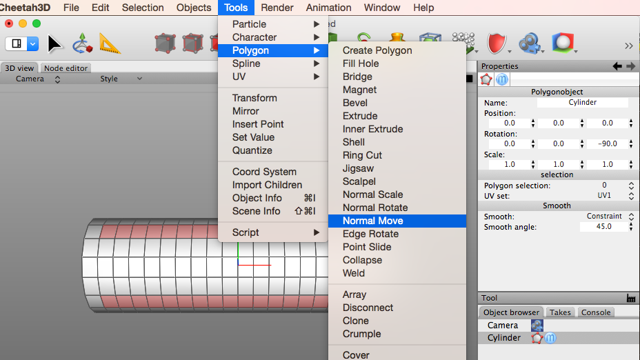
Convert the parametric cylinder object into a regular mesh object by double-clicking on the green cylinder icon in the Object Browser tab. Once you have converted the parametric object into a mesh, the green icon will turn into a polygon icon. (Circled in red.) Once you have the mesh, switch C3D into Polygon Mode and select every 4th row of polygons as shown. (Note: Don't select the first and last polygon of each row)

Step 3:
With every 4th row of polygons still selected, Choose Tools -> Polygon -> Normal Move. This will activate the Normal Move tool for use in the next step.
Step 4:
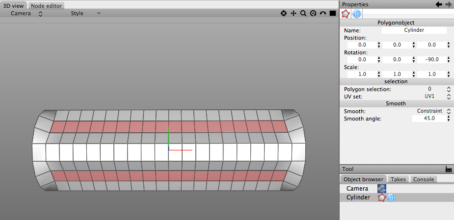
Click and drag your mouse to move the selected polygons (or normals) "inward" to create a slight bevel. If you go the wrong way, just undo the change and repeat by dragging in the opposite direction.
Step 5:
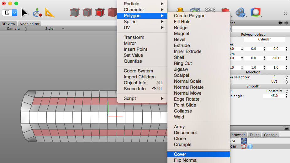
With every 4th row of polygons still selected, choose Tools -> Polygon -> Cover. This will create a copy of the vertices and edges of the select polygons in their current location. Nothing obvious will appear on the model at this point, but you will see the effect of the "cover" in the next step.
Step 6:
With the polygons still selected, switch back to the "Normal Move" tool and move the polygons inward slightly. (For a visual of this, refer back to Steps 3 and 4.) If moving the polygons simply increases the size of your original bevel, you have not successfully used the "Cover" tool. Once you have moved the normals inward, as shown below, add a Subdivision Modifier to the model by selecting Subdivision from the modifier list.
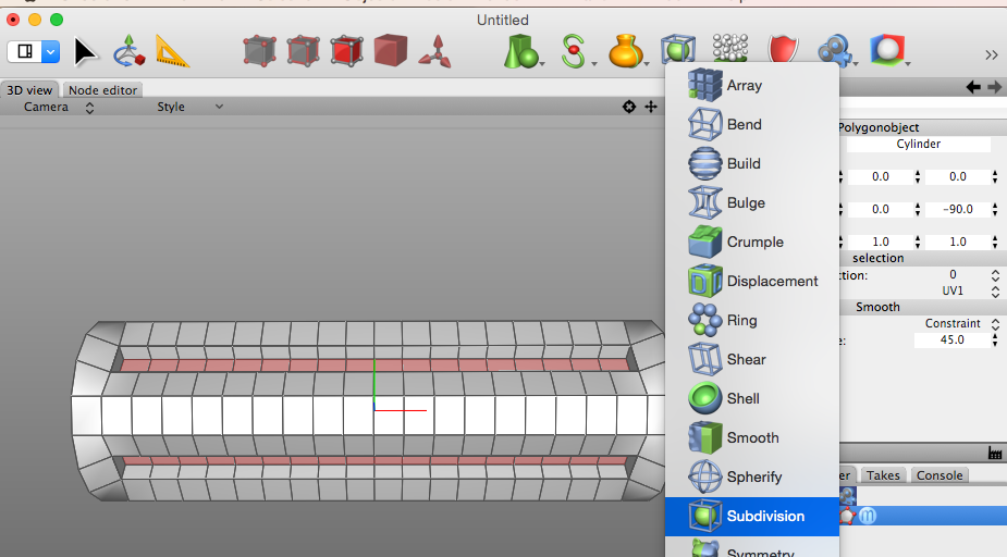
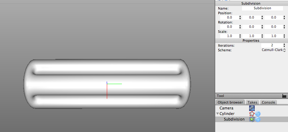
Step 7:
This is the final result of your screwdriver handle. This is the same type of model I created for the render shown at the beginning of this post. The subdivision modifier is non-destructive. That means you can continue to edit your original low-polygon mesh, and the subdivision modifier will continue to smooth it out by adding additional geometry dynamically. The default subdivision scheme is Catmull-Clark at 2 iterations which is a good default setting.
This completes the tutorial for "box" modeling the screwdriver handle with inset channels along the side and using Subdivision to smooth out the mesh with additional geometry. I hope you found this useful and that it helps you progress in understanding 3D modeling and Cheetah3D. Don't be shy if you get stuck on something or want to share your progress. Post a question on the forum! You will surely get an answer. I have found the C3D user community to be very supportive and a real asset to learning about 3D modeling.
Cheers!